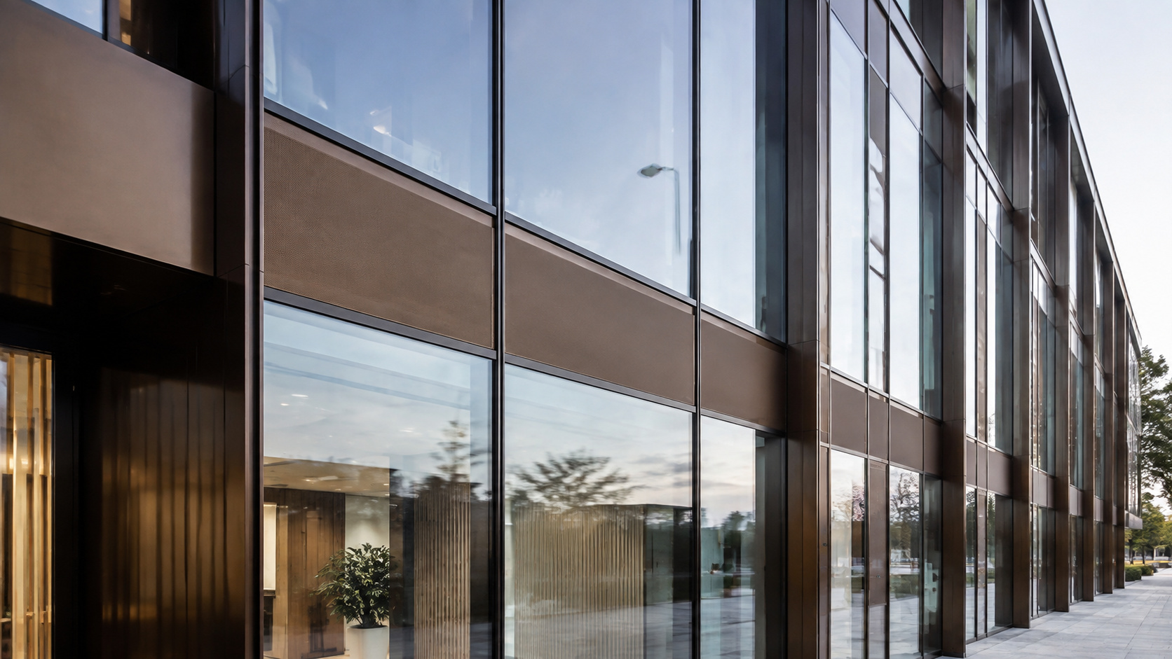
Explore solar glass and building-integrated energy.
Make the façade interfaces explicit.
For high-rise and façade projects, solar glazing must be evaluated within the envelope strategy. A render communicates visual intent; it cannot establish glass, electrical or building compliance.
What belongs in the design brief?
Elevations, orientation, shading context, vision/spandrel zones, desired transparency and module sizes. Include the façade performance brief and the project stage so material options can be assessed on the same basis.
Which interfaces need coordination?
Glass and framing, structure, weather seals, junction access, cable risers, inverter spaces and replacement logistics. Allocate façade and electrical responsibilities rather than leaving the boundary implicit.
What evidence should be requested?
Product samples, electrical characteristics, glass configuration, connection details and relevant test/certification documents. Suitability—including applicable safety and façade requirements—must be checked by the project team for the selected product and use.
Technical details.
System integration+
Connect the façade to the building.
The indicative string-inverter pathway shows local façade collection joining a coordinated DC cable route, then inverter conversion and building distribution. Product and project conditions determine the final topology.
System connections
From generation to building use.
BIPV glassDC generation
String inverterConverts DC to AC
Main switchboardAC connection point
Building loadsElectricity used on site
At the switchboard: ↔ Grid
DC generation AC distribution · ↔ two-way connectionIllustrative connections, not live energy data.Design notes
Glass connections and DC collection routes require product-specific coordination. Metering, protection and isolation are omitted. Backup requires a separately designed arrangement. This is not a construction drawing.
Design considerations+
Resolve the interfaces early.
Module proportions, glass appearance and junction locations are connected decisions. A coordinated BIPV brief gives the architectural and technical teams a common starting point.
Material intent
Establish the desired transparency, tint, dimensions and façade rhythm before narrowing product choices.
Physical interfaces
Coordinate mullions, structure, seals, cable paths and replacement access.
Technical pathway
Define collection zones, inverter locations, risers and distribution responsibilities.
FAQs & enquiry checklist+
Are technical downloads available?+
Project-specific information should be requested through a technical discussion. The site only links to material that exists; product certification, samples and detailed drawings need to be confirmed for the chosen system.