Demand before capacity
Review interval consumption, operating hours and planned load changes. Separate electricity used on site from possible exports and confirm which meter receives the generation.
Commercial PV
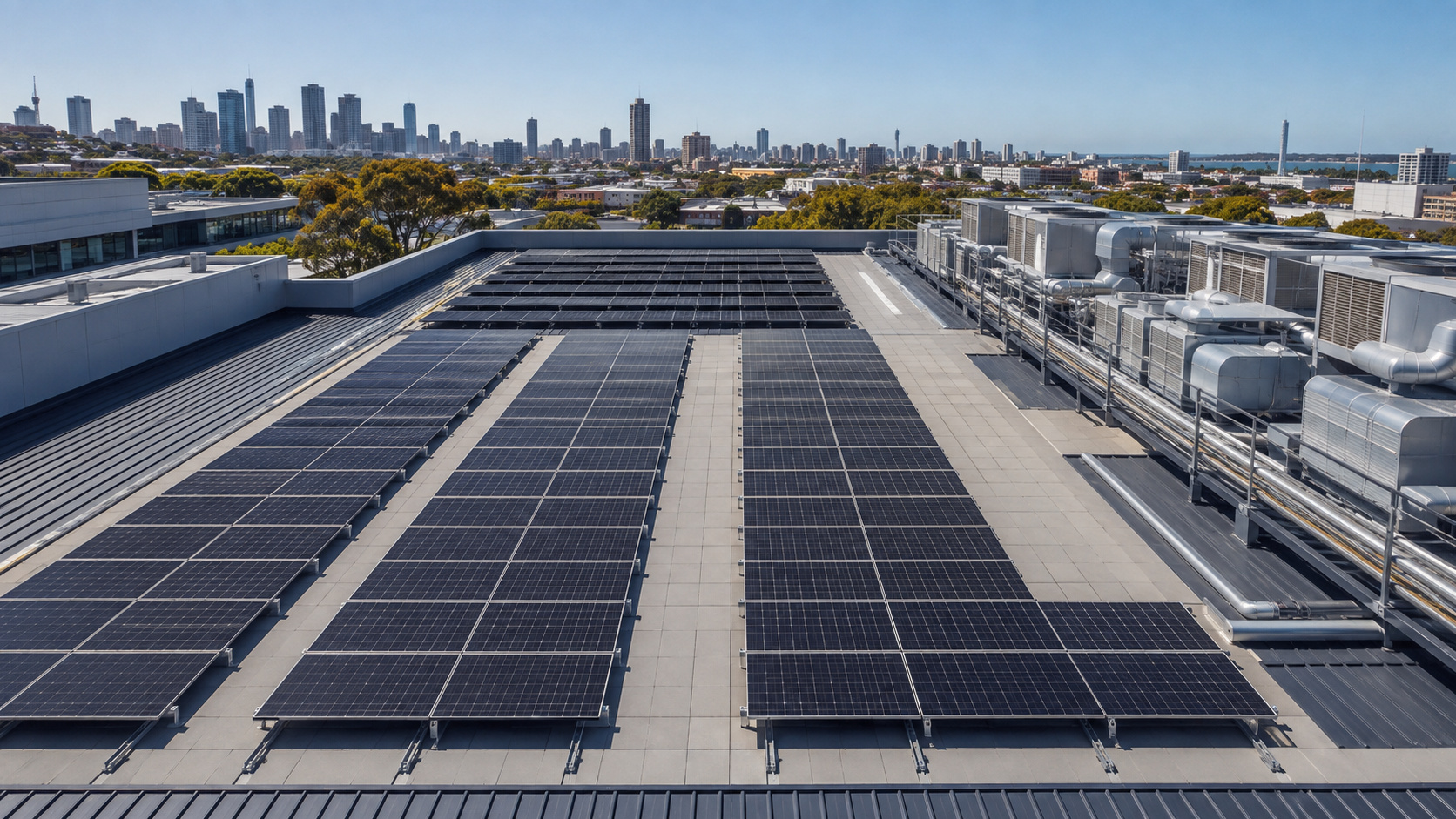
Assess rooftop PV against the operating load, the available space and the electrical connection—not roof area alone.
Operating context
Review interval consumption, operating hours and planned load changes. Separate electricity used on site from possible exports and confirm which meter receives the generation.
Review roof condition, structure, plant and access zones, shading, cable routes and switchboard capacity. Resolve lease, ownership and connection constraints early.
Compare layouts, equipment, generation assumptions, export conditions, electrical works, monitoring, warranties and maintenance on the same scope.
Selection framework
Plans, roof condition, access and existing electrical information.
Available interval data, current tariffs, operating hours and expected changes.
Energy recipient, capital-work timing, ownership responsibilities and acceptable disruption.
System integration
From generation to building use.
At the switchboard: ↔ Grid↔ Optional battery + inverter
Storage is shown as a separate AC-coupled branch. Metering, protection and isolation are omitted. Backup requires a separately designed arrangement. This is not a construction drawing.
Before a proposal
Bring the site location, available electricity data, current equipment information and the intended outcome. Record missing information and confirm the assessment scope before relying on a system size or financial estimate.
A building-first approach to commercial solar
System sizing begins with the building’s energy demand and operating profile.
Roof area, structure, access, switchboards, metering and export constraints influence the design.
Clearly defined assumptions allow commercial solar proposals to be compared properly.
Where relevant, rooftop PV can be assessed together with BIPV and battery storage.
Read the proposal
The rated capacity describes equipment under specified conditions. It is not the building’s annual electricity supply.
An estimate needs site orientation, shading and loss assumptions. Compare expected generation with interval demand to distinguish direct use, export and curtailed energy.
Separate avoided purchases from export revenue. Include the actual tariff, connection conditions, maintenance and replacement assumptions; test changed prices and loads instead of relying on a single payback figure.
Further reading: Australian Government / Solar system sizing ↗